10/14-10/16
- Kimberly Dao
- Oct 16, 2025
- 2 min read

Tuesday
On Tuesday, I milled the word clock's PCB. It turned out very smoothly and after it finished, I cleaned up on the copper strands that suck to the board. After I cleaned it, I checked each connection. Every connection had a connection and I was glad that nothing broke during the mill. After checking all of the connections, I showed Mr. Chirsty the product. He said it looked great so then I started to solder each component. I didn't finish it.

Wednesday
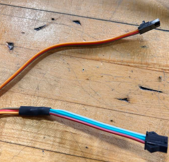
I spent the whole day soldering the PCB as there were a lot of holes for each components. After I finished I was proud of my work and then wanted to test out the board if it can power the word clock. However, I stumbled on a problem. The connection from the first LED block doesn't have the correct polarized connection that is needed to attach onto the PCB. I had to use a spare connecter and then strip and crimp a polarized connecter. First, I soldered a longer wire onto the connecter that is being used to connect to the first LED block. After I finished soldering it, I used heat shrinks to wrap around each connection. I then wrapped the them in a bigger heat shirk to keep them all together. I labeled the power and ground wire.


Thursday
I tried my best to strip and crimp but I was having a lot of issues. The crimp and wires were being a hassle and wouldn't stay together. When I finally did it, I realized that I reversed the pattern so then needed to redo it in order to have the power and ground match with the power and ground connections on the PCB board. After one last try, I was able to finally to connect them properly and in the right corresponding spots.


Comments